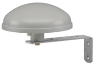
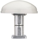
DCF77 Antenna 4417 / 4418 / 4420 / 4436 / 4437
Short Description
Antenna structure
All hopf antennas are directional active antennas and of the same electrical design. Ferrite antennas are used for the frequencies in the long-wave range to keep the antennas small. The oscillating circuit in the antenna, made of a wired ferrite rod and various capacitors, is tuned to 77.5 kHz.
The features of the oscillating circuit depend mainly on the ferrite rod. Temperature changes influence the permeability of the ferrite rod and thus the mid-frequency of the tuned oscillating circuit for the DCF77 signal.
The output voltage of the oscillating circuit is fed to an amplifier with definite input resistance. Behind the amplifier there is an adaptation to the antenna cable.
Types of antennas
The following types of antennas for the different purposes are available:
- FG443600 Indoor antenna
- FG441700A Outdoor antenna for the flat roof installation
- FG441800A Outdoor antenna for the wall installation
- FG442000 Outdoor antenna for the pole installation
- FG443700 Outdoor antenna with non-directional reception for mobile operations
Indoor antenna FG443600
This antenna can be used in buildings away from sources of interference for the DCF77-reception. e.g. TVs, monitors, terminals, in-house-LAN, electrical engines etc.
Also the construction of the building has to be taken into consideration. Reinforced concrete buildings and fairing plates attenuate considerably the DCF77-signal and cause a bad signal / noise ratio.
The antenna, which can be turned by 360°, is screwed to a wall bracket made of zinc-coated steel.
Outdoor antennas
Mostly radio controlled clock systems are running with an outdoor antenna. Whereas the surroundings of the indoor antenna can change because of changing technical operations in the rooms, the conditions for the outdoor antenna remain nearly constant.
For rough weather conditions we supply a very robust outdoor antenna. It is housed in a round weatherproof plastic casing. The different antennas differ in their mechanical structure only.
The mechanical construction is made of a sturdy, anodised aluminum or die-cast aluminum designed to withstand strong wind. The antenna cable leaves the casing at the bottom.
Technical Data
| General information | |
|---|---|
| voltage supply via antenna cable: | +1,7 to +5V DC |
| differential output resistance: | 50 Ω |
| amplification: | 26 (20) dB |
| antenna cable: | RG59 compatible |
| cable length (delivery status): | indoor antenna: 10 m outdoor antenna: 20 m |
| max. cable length without multi aerial amplifier: | theoretically: 500 m recommended: 250 m |
| max. cable length with multi aerial amplifier: | theoretically: 1000 m recommended: 500 m |
| plastic: | light proof |
| wind stress outdoor antenna: | max. 180 km/h |
| band width: | 4 kHz |
| indoor antenna 4436 | |
| humidity: | 95% non-condensing |
| protection class: | IP50 |
| temperature range 3 dB limit: | |
| operation: | 0°C to +50° C |
| storage: | -50° C to +85° C |
| outdoor antennas 4417, 4418, 4420, 4437 | |
| humidity: | 100% |
| protection class: | IP65 |
| temperature range 3 dB limit: | |
| operation: | -30° C to +80° C |
| storage: | -50° C to +85° C |
Pictures
Downloads
PDF documents
Software and Driver
- For this product there is no Software / Driver available.


